Email Us
News

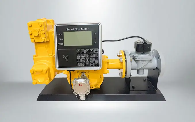
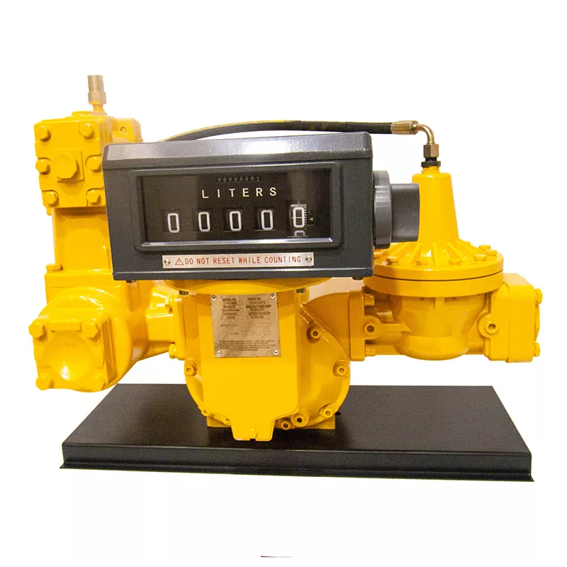
​What should we pay attention to when installing a flow meter?

The use of flow meters saves us a lot of trouble, but to install a flow meter properly, the following points should be noted:

flow meters

1.Site assessment and preliminary configuration

Location selection must prioritize avoidance of mechanical vibration sources and electromagnetic interference zones—hydraulic damping mounts (specified in ISO 10816-3) are mandatory where pipeline vibration exceeds 0.1mm amplitude, and 0.8mm Mu-metal shielding is required within 1.5m of 380V motors (a documented pump plant incident showed 12% monthly deviation in electromagnetic meters without shielding). Liquid pipelines require a minimum 3° upward slope (52.4mm rise per meter) verified by 0.02mm/m precision levels, with Spirax Sarco ARV20 vent valves (≥5L/min capacity) installed at U-bend peaks—a water treatment plant experienced 37 hours of electromagnetic meter failure due to vapor lock from insufficient slope. Flow direction alignment must be maintained within ≤2° error (laser-alignment verified); reverse installation of vortex meters permanently damages shedder bars.

2.Meter body installation and flow regime assurance

Straight-run pipe lengths are categorized by disturbance source: ≥10 pipe diameters upstream of 90° elbows (e.g., 1.0m for DN100 pipe), ≥20 diameters upstream of pumps/valves. The Rosemount 1495 tube bundle flow conditioner may reduce straight-run requirements to 5 diameters where space is constrained (a refinery’s V-cone meter recorded -8% systematic error from inadequate straight pipes). Full-pipe operation is used for make sure that through dual mechanisms: sensors fixed at a 30° upward orientation in horizontal pipes (optimal bubble escape angle), and outlet backpressure valves maintaining >1.25× fluid vapor pressure (>31kPa for 70°C hot water systems)—a district heating station recorded 63% ultrasonic signal loss due to insufficient backpressure. Forty-mesh stainless steel filters (capturing ≥380μm particles, auto-backwash at ΔP>0.5Bar) must be installed 5 pipe diameters upstream—a sugar refinery’s turbine meter seized when sucrose crystals jammed its bearings without filtration.

3. System integration and final validation

Phase-separation devices are configured by media type: gas lines require condensate pots (volume ≥5% pipe volume) at 1 pipe diameter upstream paired with TLV J3X traps, liquid lines need Swagelok ASC-1 degassers at pipeline crowns (gas volume fraction <0.5%), and steam lines require supplementary Yoshitake FT43H thermodynamic traps (a pharmaceutical plant recorded ±18% density drift in Coriolis meters from wet steam). Pipeline thermal expansion is calculated as ΔL=12.3×10⁻⁶×L×ΔT (1.23mm/m for 304 SS pipes at ΔT=100°C), with Ω-expansion joints compensating ≥1.5ΔL (Witzenmann RBK series). Fixed supports spaced ≤15m apart and sliding supports with PTFE liners are essential (a power plant recorded helium leak exceedances from flange stress fractures). Bypass systems employ a triple-valve train (Z41H gate valve + Q41F ball valve + J41Y globe valve, leakage class ANSI CLASS VI), supplemented with dual isolation valves for online zero calibration (a refinery incurred $82,000 maintenance loss from bypass deficiencies). Final inspection enforces three non-negotiable protocols: ultrasonic transducer removal during welding (80°C temperature limit), dedicated grounding rods for electromagnetic meters (1.5m copper electrode, resistance <4Ω), and helium leak testing at 1.5× working pressure (<1×10⁻⁶ mbar·L/s leakage rate per ASME MFC-3M Section 4.7).


Is not easy,right?However, once we have noted these points, flow meters can be put to better use.


Related News
Mobile
+86-15671022822
Address
No. 460, Jinhai Road, Economic And Technological Development Zone, Wenzhou, Zhejiang, China
X
We use cookies to offer you a better browsing experience, analyze site traffic and personalize content. By using this site, you agree to our use of cookies. Privacy Policy
Reject Accept